
Innis Well Drilling LLC offers commercial and residential well drilling and pump installation services in most of Hancock, Penobscot, and Piscataquis counties in Maine. This page of our website offers an in-depth look at what goes into a couple of our services.
Underreaming in a Nutshell
Normally, we begin drilling a well by hammering an 8 1/2 inch hole to the depth that we need to set the casing. In unstable formations, this technique is insufficient for keeping the hole from caving in. In these situations, we use our underreamer system, which drives the casing and drills at the same time. This ensures a clean hole and a properly sealed well. It employs a more expensive casing crown and is usually more time consuming than standard drilling techniques.
Welding the Casing Crown

Welding the Casing Crown
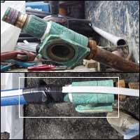
The first step when using the underreamer system is to weld the crown to the casing so it may drill down the hole by turning independent of the casing. Notice the buttons covering the leading edge of the crown? These are carbides, the same super-hard drilling buttons that cover the drill bit.
Loading the Drill Rod

Loading the Drill Rod
After welding the casing crown, we load the drill rod into the casing. On the end of the rod, we have a special drill bit which locks into the crown, allowing the drill bit and the crown to turn simultaneously, drilling the hole and setting the casing at the same time. This simultaneous drilling technique is critical in formations, which tend to cave in before the casing goes into the hole.
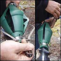
Attaching the Diverter

After loading the drill rod, we must attach the diverter to the casing. The diverter slides over the top of the rod and casing, creating a seal around it and diverting the drillings away from the drilling rig. Underreaming would be a bit messy if we did not have the diverter!
Hooking the Hose to the Diverter

The diverter channels the drillings away from the drilling rig through a heavy-duty hose, able to handle the volume and pressure of the material exiting through it. Before drilling, we must attach the hose to the diverter.
Monitoring the Hose
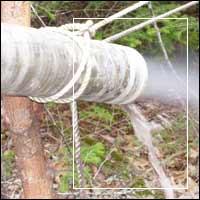
By keeping an eye on the material coming out of the hose, we can see exactly what kind of formation we are in; sand, clay, bedrock, etc. In addition, we observe the speed of drilling, the sound, and other factors to determine when the casing is securely in bedrock and underreaming is no longer necessary.
Pump Systems
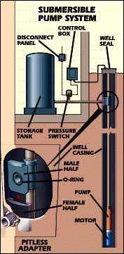
The pump system is the mechanism that delivers water from the well to the house. Water is sucked into the submersible pump, pushed up the pipe in the well, through the pitless adapter, along the underground waterline and into the pressure tank. When the water pressure inside the pipe reaches a certain level (usually 60 PSI) the pressure switch shuts the pump off, and water in the tank is stored for household use. When the tank is depleted and water pressure drops to a certain level (usually 40 PSI) the pump turns back on and the process starts over again.
Installing the Pump
Connecting the Pump to the Drop Pipe
The first step in installing the submersible pump is connecting the pump to the drop pipe. Typically, we use a 1 by 1 1/4 inch barbed adapter and two 1 inch clamps to connect the pump to the pipe. Thread sealant is used to seal the threads on the pump and the clamps are installed in opposing directions. The clamps are then covered with electrical tape to protect the pump wire.
Splicing the Pump Wire to the Pump
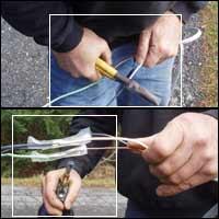
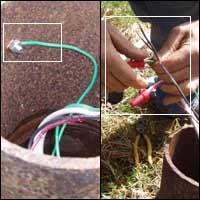
Next, we use a splice kit to join the motor lead on the pump to the pump wire. The ground and power feed wires both connect with butt connectors. The connection is then sealed from water intrusion using a torch and heat shrinks.
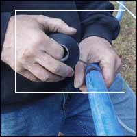
Protecting the Splice
 A chain is only as strong as its weakest link, and on our length of wire, it is important to protect the splice we have just made. For this reason, we make an S shaped coil at the splice to protect it from excessive tension. Next, we cover the connection with plenty of electrical tape to protect against chaffing.
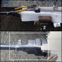
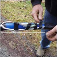
Sizing Up the Torque Arrestor
 The torque arrestor keeps the pump, pipe, and wire from rubbing on the sides of the well when the pump kicks on, ensuring the longevity of your pump system. To install the torque arrestor, we place it on the pipe just above the pump and clamp the side closest to the pump. Using a set of calipers as a guide expand it slightly larger than the diameter of the well (typically 6 inches) and clamp the other side of the torque arrestor in place.
Taping the Wire to the Pipe
To keep the remaining pump wire away from the sides of the well, we secure it to the pipe. Starting at the torque arrestor, tape the wire to the pipe at 3 to 5 foot increments. Although State of Maine Guidelines allow for 10-foot increments, we feel that 3 to 5 feet is a safer bet. Additionally, wire guards are placed around the pipe at 50-foot increments to prevent it from chaffing.
Putting the Pump in the Well
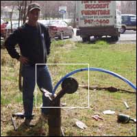
After taping the wire to the pump, we put the pump down the well using a special wheel. It is a good idea during this time to wipe off any dirt or debris that has accumulated on the pipe, as this could contaminate the water in the well. Before reaching the end of the pipe, we put a clamp on it so that the pitless adapter can be installed.
Attaching the Pitless Adapter
Before connecting the male half of the pitless adapter to the pipe, we screw it onto the T-Bar so that it may be lowered into the well. Next we connect the two using a 1 inch barbed adapter and two 1 inch clamps. We use thread sealant and install the clamps in opposite directions for the best grip. The clamps are covered in tape and the wire is taped to the back of the pitless adapter. Food grade lubricant is applied to the mating surfaces of fitting.
Hooking Up to the Feed Wire
After securing the pitless adapter in the well and removing the T-Bar, the last step in installing the pump is to connect the pump wire in the well to the feed wire in the conduit. Under normal circumstances, we use wing nut connectors to connect the wires, but if the static water level in the well is high, we use a waterproof splice kit. Additionally, the ground wire is attached to the casing for safety purposes. The well is then chlorinated to 50 PPM with calcium chloride tablets as required by state rules.
To learn more about our well drilling services, contact us today.